本章承接第 14 章的非阻塞程式設計,進一步說明 Arduino 如何使用 Interrupt(中斷)即時回應按鍵、脈衝與快速事件。
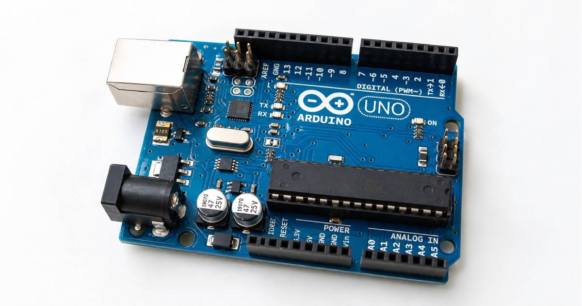
內容以 Arduino Uno R3 為主要示範環境,涵蓋外部中斷腳位、attachInterrupt()、ISR、volatile、按鍵去彈跳、脈衝計數、轉速計算與共享變數的安全存取。
中斷適合處理短暫且不能漏掉的事件,但 ISR 必須保持簡短,不可在其中執行 delay()、大量 Serial 輸出或耗時工作。
本章學習目標
- 了解 Interrupt(中斷)的基本概念。
- 分辨輪詢(Polling)與中斷的差異。
- 認識 Arduino Uno 的外部中斷腳位。
- 正確使用 attachInterrupt() 與 detachInterrupt()。
- 了解 ISR(Interrupt Service Routine,中斷服務常式)的設計原則。
- 正確使用 volatile 關鍵字。
- 使用中斷偵測按鍵、旋轉編碼器與脈衝訊號。
- 避免在中斷程式中使用不適合的函式。
- 理解按鍵彈跳與中斷誤觸發問題。
什麼是 Interrupt 中斷
Interrupt 中文稱為中斷。當 Arduino 正在執行主程式時,如果外部發生重要事件,中斷機制會暫停目前工作,立即執行指定的中斷服務常式,處理完成後再回到原本位置繼續執行。
常見中斷事件包括按鍵按下、感測器脈衝、旋轉編碼器轉動、流量計輸出、馬達轉速感測器脈衝與計時器事件。
- Arduino 正在執行主程式。
- 外部事件發生。
- 主程式暫時停止。
- 執行 ISR。
- 中斷處理完成。
- 返回主程式原本位置繼續執行。
| 項目 | 說明 |
|---|---|
| 英文 | Interrupt |
| 中文 | 中斷 |
| 主要用途 | 即時處理外部事件 |
| 設定函式 | attachInterrupt() |
| 停用函式 | detachInterrupt() |
| 中斷處理函式 | ISR |
| Uno 外部中斷腳位 | D2、D3 |
| 常用觸發方式 | RISING、FALLING、CHANGE、LOW |
為什麼需要中斷
一般 Arduino 程式常在 loop() 中不斷讀取輸入腳位,這種方式稱為 Polling(輪詢)。程式簡單時,輪詢容易理解且容易除錯。
當主程式同時更新 LCD、讀取多個感測器、處理 Serial、控制馬達、執行長時間運算或使用 delay() 時,短暫脈衝可能在兩次檢查之間消失,中斷便能提高事件反應速度。
void loop()
{
  if (digitalRead(2) == LOW)
  {
    Serial.println("Button pressed");
  }
}
輪詢與中斷的差異
| 比較項目 | 輪詢 Polling | 中斷 Interrupt |
|---|---|---|
| 事件來源 | 主程式主動檢查輸入狀態 | 硬體事件主動通知微控制器 |
| 反應速度 | 受 loop() 執行時間影響 | 事件發生時立即進入 ISR |
| 適用情境 | 一般按鍵、慢速感測器、簡單選單 | 短脈衝、轉速、流量、即時事件 |
| 優點 | 流程容易理解、追蹤與除錯 | 反應快、不必持續檢查腳位 |
| 缺點 | 主程式忙碌時可能漏掉事件 | 設計較複雜,ISR 有許多限制 |
適合使用中斷的情況
- 計算旋轉編碼器脈衝。
- 計算馬達轉速。
- 接收流量計或霍爾感測器脈衝。
- 偵測短時間數位訊號。
- 精準記錄事件發生次數。
- 偵測緊急停止訊號。
- 處理定時器事件。
不一定需要中斷的情況
- 一般 LED 開關。
- 緩慢變化的溫度感測器。
- 每秒讀取一次的資料。
- 簡單按鍵選單。
- LCD 畫面切換。
中斷不是越多越好。只有在需要快速反應,或輪詢可能漏掉事件時,才應優先考慮使用。
Arduino Uno 的外部中斷腳位
| Arduino 腳位 | 外部中斷編號 |
|---|---|
| D2 | INT0 |
| D3 | INT1 |
不同 Arduino 開發板的外部中斷腳位可能不同,因此不建議直接在程式中寫死中斷編號。
建議使用 digitalPinToInterrupt(pin) 將 Arduino 腳位轉換成中斷編號,讓程式更容易移植。
attachInterrupt(
  digitalPinToInterrupt(2),
  handleInterrupt,
  FALLING
);
attachInterrupt() 基本語法
attachInterrupt(
  digitalPinToInterrupt(pin),
  ISR,
  mode
);| 參數 | 說明 |
|---|---|
| pin | 外部中斷輸入腳位,建議透過 digitalPinToInterrupt(pin) 轉換 |
| ISR | 中斷發生時執行的函式 |
| mode | LOW、CHANGE、RISING 或 FALLING 觸發方式 |
中斷觸發模式
LOW 低電位觸發
當腳位維持 LOW 時觸發。只要訊號持續為低電位,就可能反覆進入 ISR,因此初學階段較少使用。
attachInterrupt(
  digitalPinToInterrupt(2),
  handleInterrupt,
  LOW
);
CHANGE 狀態改變觸發
當訊號由 LOW 變 HIGH 或由 HIGH 變 LOW 時觸發,適合旋轉編碼器、脈衝寬度量測及同時偵測上升緣與下降緣。
attachInterrupt(
  digitalPinToInterrupt(2),
  handleInterrupt,
  CHANGE
);
RISING 上升緣觸發
當訊號由 LOW 變成 HIGH 時觸發,適合偵測正向脈衝的上升緣。
attachInterrupt(
  digitalPinToInterrupt(2),
  handleInterrupt,
  RISING
);
FALLING 下降緣觸發
當訊號由 HIGH 變成 LOW 時觸發。按鍵搭配 INPUT_PULLUP 時,放開為 HIGH、按下為 LOW,因此按下瞬間通常使用 FALLING。
attachInterrupt(
  digitalPinToInterrupt(2),
  handleInterrupt,
  FALLING
);
第一個中斷實驗:按鍵計數器
| 元件 | 數量 |
|---|---|
| Arduino Uno R3 | 1 |
| 按鍵 | 1 |
| Breadboard | 1 |
| 杜邦線 | 若干 |
使用 Arduino 內部上拉電阻,D2 經按鍵接到 GND,不需要額外外接上拉電阻。
const int BUTTON_PIN = 2;
volatile unsigned long pressCount = 0;

void setup()
{
  pinMode(BUTTON_PIN, INPUT_PULLUP);
  Serial.begin(9600);

  attachInterrupt(
    digitalPinToInterrupt(BUTTON_PIN),
    handleButtonPress,
    FALLING
  );
}

void loop()
{
  Serial.print("Press count: ");
  Serial.println(pressCount);
  delay(500);
}

void handleButtonPress()
{
  pressCount++;
}
每當按鍵訊號由 HIGH 變成 LOW,ISR 就會把 pressCount 加一。此範例主要用來理解中斷流程,後續會改善共享變數讀取與按鍵彈跳問題。
什麼是 ISR
ISR 是 Interrupt Service Routine 的縮寫,中文稱為中斷服務常式。
當中斷發生時,Arduino 暫停 loop(),執行 ISR,完成後再回到主程式。ISR 的核心原則是越短越好。
ISR 適合執行的工作
- 設定旗標。
- 增加計數值。
- 記錄簡單狀態。
- 儲存事件發生時間。
ISR 不適合執行的工作
- 複雜計算。
- 長迴圈。
- 更新 LCD。
- 控制大量硬體。
- 大量字串處理。
- 長時間等待。
ISR 執行太久會暫停主程式並延遲其他中斷,可能造成程式反應遲鈍、資料遺失、計時不準、通訊異常或系統卡住。
ISR 中應避免的函式
不要在 ISR 中使用 delay()
void handleButtonPress()
{
  delay(100);
  pressCount++;
}
delay() 依賴計時中斷運作,而 ISR 執行期間其他中斷通常受到限制,因此 delay() 可能無法正常工作。ISR 內不應等待。
不要在 ISR 中大量使用 Serial
void handleButtonPress()
{
  Serial.println("Button pressed");
}
Serial.print() 可能依賴緩衝區與中斷傳送資料。在 ISR 中大量輸出可能造成緩衝區塞滿、程式停住、輸出不完整或其他中斷延遲。
volatile bool buttonEvent = false;

void handleButtonPress()
{
  buttonEvent = true;
}

void loop()
{
  if (buttonEvent)
  {
    buttonEvent = false;
    Serial.println("Button pressed");
  }
}
volatile 關鍵字
若變數會同時由 ISR 修改,並由主程式讀取或修改,就應宣告為 volatile。
volatile 告訴編譯器,該變數可能隨時被另一個執行流程修改,每次存取都必須以記憶體中的實際值為準。
volatile bool buttonEvent = false;
volatile unsigned long pulseCount = 0;
使用旗標處理中斷事件
較安全的架構是讓 ISR 只設定旗標,再由 loop() 執行 LED 控制、Serial 輸出與其他完整工作。
const int BUTTON_PIN = 2;
const int LED_PIN = 9;

volatile bool buttonEvent = false;
bool ledState = false;

void setup()
{
  pinMode(BUTTON_PIN, INPUT_PULLUP);
  pinMode(LED_PIN, OUTPUT);
  Serial.begin(9600);

  attachInterrupt(
    digitalPinToInterrupt(BUTTON_PIN),
    handleButtonPress,
    FALLING
  );
}

void loop()
{
  if (buttonEvent)
  {
    buttonEvent = false;
    ledState = !ledState;
    digitalWrite(LED_PIN, ledState);

    Serial.print("LED: ");
    Serial.println(ledState ? "ON" : "OFF");
  }
}

void handleButtonPress()
{
  buttonEvent = true;
}
按鍵彈跳與誤觸發
機械按鍵在接點接觸瞬間,訊號可能在 HIGH 與 LOW 之間快速反覆變化。使用者只按一次,Arduino 卻可能收到多次中斷,這種現象稱為 Contact Bounce(接點彈跳)。
按鍵彈跳可能使 pressCount 一次增加多次,因此必須加入軟體或硬體去彈跳。
在 ISR 中進行基本時間判斷
const int BUTTON_PIN = 2;

volatile unsigned long pressCount = 0;
volatile unsigned long lastInterruptTime = 0;

const unsigned long DEBOUNCE_TIME = 50;

void setup()
{
  pinMode(BUTTON_PIN, INPUT_PULLUP);
  Serial.begin(9600);

  attachInterrupt(
    digitalPinToInterrupt(BUTTON_PIN),
    handleButtonPress,
    FALLING
  );
}

void loop()
{
  noInterrupts();
  unsigned long countCopy = pressCount;
  interrupts();

  Serial.print("Press count: ");
  Serial.println(countCopy);
  delay(500);
}

void handleButtonPress()
{
  unsigned long currentTime = millis();

  if (currentTime - lastInterruptTime >= DEBOUNCE_TIME)
  {
    pressCount++;
    lastInterruptTime = currentTime;
  }
}
millis() 可在 ISR 中讀取目前值,但 ISR 執行期間通常不會持續正常更新。可用於短時間事件判斷,不可在 ISR 內等待 millis() 改變。
較安全的旗標式去彈跳
const int BUTTON_PIN = 2;
const int LED_PIN = 9;

volatile bool interruptTriggered = false;

unsigned long lastAcceptedTime = 0;
const unsigned long DEBOUNCE_TIME = 50;
bool ledState = false;

void setup()
{
  pinMode(BUTTON_PIN, INPUT_PULLUP);
  pinMode(LED_PIN, OUTPUT);
  Serial.begin(9600);

  attachInterrupt(
    digitalPinToInterrupt(BUTTON_PIN),
    handleButtonInterrupt,
    FALLING
  );
}

void loop()
{
  if (interruptTriggered)
  {
    noInterrupts();
    interruptTriggered = false;
    interrupts();

    unsigned long currentTime = millis();

    if (currentTime - lastAcceptedTime >= DEBOUNCE_TIME)
    {
      lastAcceptedTime = currentTime;
      ledState = !ledState;
      digitalWrite(LED_PIN, ledState);

      Serial.print("LED: ");
      Serial.println(ledState ? "ON" : "OFF");
    }
  }
}

void handleButtonInterrupt()
{
  interruptTriggered = true;
}
這種設計讓 ISR 只設定旗標,時間判斷、LED 控制與 Serial 輸出都由 loop() 完成。
noInterrupts() 與 interrupts()
| 函式 | 用途 |
|---|---|
| noInterrupts() | 暫時停用全域中斷 |
| interrupts() | 重新啟用全域中斷 |
Arduino Uno 使用 8 位元微控制器。unsigned long 需要 4 Bytes,主程式讀取到一半時若 ISR 修改變數,可能得到混合且不完整的數值。
讀取多位元共享變數時,可短暫停用中斷,複製到一般變數後立即重新啟用。停用區段必須越短越好。
noInterrupts();
unsigned long countCopy = pulseCount;
interrupts();
不要在 noInterrupts() 與 interrupts() 之間執行 delay()、Serial 輸出、顯示更新或長時間運算,否則可能漏掉脈衝、影響通訊與時間計算。
detachInterrupt() 停用外部中斷
不再需要某個外部中斷時,可使用 detachInterrupt() 停用該腳位的中斷處理。
void stopButtonInterrupt()
{
  detachInterrupt(
    digitalPinToInterrupt(BUTTON_PIN)
  );
}
第二個實驗:脈衝計數器
流量感測器、霍爾感測器、馬達轉速感測器、光電編碼器、風速計與電能計量裝置常以脈衝代表事件。
const int PULSE_PIN = 2;
volatile unsigned long pulseCount = 0;

void setup()
{
  pinMode(PULSE_PIN, INPUT_PULLUP);
  Serial.begin(9600);

  attachInterrupt(
    digitalPinToInterrupt(PULSE_PIN),
    countPulse,
    FALLING
  );
}

void loop()
{
  noInterrupts();
  unsigned long countCopy = pulseCount;
  interrupts();

  Serial.print("Pulse count: ");
  Serial.println(countCopy);
  delay(1000);
}

void countPulse()
{
  pulseCount++;
}
每收到一個下降緣脈衝,pulseCount 就增加一次。主程式以短暫原子區段複製計數值,避免讀取不完整資料。
第三個實驗:測量每秒脈衝數
const int PULSE_PIN = 2;

volatile unsigned long pulseCount = 0;

unsigned long previousMillis = 0;
const unsigned long REPORT_INTERVAL = 1000;

void setup()
{
  pinMode(PULSE_PIN, INPUT_PULLUP);
  Serial.begin(9600);

  attachInterrupt(
    digitalPinToInterrupt(PULSE_PIN),
    countPulse,
    FALLING
  );
}

void loop()
{
  unsigned long currentMillis = millis();
  unsigned long elapsedTime =
    currentMillis - previousMillis;

  if (elapsedTime >= REPORT_INTERVAL)
  {
    previousMillis = currentMillis;

    noInterrupts();
    unsigned long pulseCopy = pulseCount;
    pulseCount = 0;
    interrupts();

    float pulsesPerSecond =
      pulseCopy * 1000.0 / elapsedTime;

    Serial.print("Pulses per second: ");
    Serial.println(pulsesPerSecond, 2);
  }
}

void countPulse()
{
  pulseCount++;
}- 記錄本次報告與上次報告之間的實際經過時間。
- 安全複製 pulseCount,並將共享計數值歸零。
- 使用實際經過毫秒數換算每秒脈衝數,避免主程式延遲造成誤差。
從脈衝計算轉速
感測器每轉一圈輸出一個脈衝時,RPM 等於每秒脈衝數乘以 60。pulsesPerSecond 應使用實際經過時間換算,而不是假設每次量測都剛好等於一秒。
float rpm = pulsesPerSecond * 60.0;若每轉一圈產生多個脈衝,則必須再除以每圈脈衝數。
const int PULSES_PER_REVOLUTION = 20;

float rpm =
  pulsesPerSecond * 60.0 /
  PULSES_PER_REVOLUTION;
第四個實驗:中斷控制 LED 狀態
const int BUTTON_PIN = 2;
const int LED_PIN = 9;

volatile bool buttonEvent = false;
bool ledState = false;

void setup()
{
  pinMode(BUTTON_PIN, INPUT_PULLUP);
  pinMode(LED_PIN, OUTPUT);
  Serial.begin(9600);

  attachInterrupt(
    digitalPinToInterrupt(BUTTON_PIN),
    handleButtonInterrupt,
    FALLING
  );
}

void loop()
{
  if (buttonEvent)
  {
    noInterrupts();
    buttonEvent = false;
    interrupts();

    ledState = !ledState;
    digitalWrite(LED_PIN, ledState);

    Serial.print("LED state: ");
    Serial.println(ledState ? "ON" : "OFF");
  }
}

void handleButtonInterrupt()
{
  buttonEvent = true;
}- 中斷發生。
- ISR 設定事件旗標。
- loop() 安全取得並清除旗標。
- 主程式執行 LED 控制與 Serial 輸出。
中斷與旋轉編碼器
旋轉編碼器常輸出 A、B 兩組方波,透過兩組訊號的先後順序,可判斷順時針、逆時針與旋轉步數。簡化接線為 CLK 接 D2、DT 接 D4、GND 接 GND。
const int ENCODER_CLK = 2;
const int ENCODER_DT = 4;

volatile long encoderPosition = 0;

void setup()
{
  pinMode(ENCODER_CLK, INPUT_PULLUP);
  pinMode(ENCODER_DT, INPUT_PULLUP);
  Serial.begin(9600);

  attachInterrupt(
    digitalPinToInterrupt(ENCODER_CLK),
    handleEncoder,
    FALLING
  );
}

void loop()
{
  noInterrupts();
  long positionCopy = encoderPosition;
  interrupts();

  Serial.print("Position: ");
  Serial.println(positionCopy);
  delay(100);
}

void handleEncoder()
{
  if (digitalRead(ENCODER_DT) == HIGH)
  {
    encoderPosition++;
  }
  else
  {
    encoderPosition--;
  }
}
此為入門版範例。實際旋轉編碼器可能有接點彈跳、多次邊緣、方向誤判與快速旋轉漏計數,進階專案可採完整狀態解碼或專用函式庫。
外部中斷與 Pin Change Interrupt
Arduino Uno 除了 D2、D3 的標準外部中斷外,ATmega328P 還支援 Pin Change Interrupt(腳位變化中斷),可讓更多數位腳位偵測狀態改變。
Pin Change Interrupt 設定較複雜,通常需要操作暫存器或使用函式庫,而且多個腳位可能共用同一個 ISR,程式必須自行判斷是哪個腳位發生變化。初學階段建議先熟悉 D2 與 D3。
中斷優先順序與嵌套
微控制器可能同時具有外部中斷、Timer、UART、ADC 與 SPI 等中斷來源。一般 Arduino 程式不需要手動設定優先順序,但 ISR 仍應保持簡短,避免長時間阻擋其他中斷。
Arduino Uno 一般在執行 ISR 時不會立即進入其他 ISR。初學者不應在 ISR 內呼叫 interrupts() 允許中斷嵌套,否則會大幅增加程式複雜度與風險。
中斷與 millis()、micros()
- millis() 與 micros() 本身依賴 Timer 中斷更新。
- ISR 執行期間,millis() 不會持續正常增加。
- delay() 在 ISR 中無法正常工作。
- micros() 在很短時間內可能仍可提供讀值,但不應用於長時間等待。
- ISR 應只記錄事件,不在其中等待時間經過。
共享變數與不可分割存取
若 ISR 修改 volatile unsigned long pulseCount,而 loop() 同時讀取,主程式可能先讀取部分 Byte,接著 ISR 修改變數,再讀取剩餘 Byte,最後得到混合結果。
使用 noInterrupts() 與 interrupts() 保護必要的讀寫區段,可形成 Atomic Access(不可分割存取)。
noInterrupts();
unsigned long countCopy = pulseCount;
interrupts();
bool 或 byte 是否需要停用中斷
在 Arduino Uno 上,單一 byte 或 bool 通常可以一次完成讀寫,因此較不容易讀到一半。
若操作包含讀取後立刻清除,例如讀取 eventFlag 後設為 false,仍可能在兩個動作之間再次發生中斷。要求嚴謹時,可把複合操作放在短暫原子區段內。
noInterrupts();
bool eventCopy = eventFlag;
eventFlag = false;
interrupts();
推薦的中斷程式架構
- ISR 只記錄事件,例如設定旗標或增加計數。
- 主程式使用短暫原子區段取得共享資料。
- 主程式在中斷區段外完成顯示、通訊、運算與硬體控制。
void handleInterrupt()
{
  eventFlag = true;
}

void loop()
{
  noInterrupts();
  bool eventCopy = eventFlag;
  eventFlag = false;
  interrupts();

  if (eventCopy)
  {
    updateLed();
    updateDisplay();
    sendSerialReport();
  }
}
綜合實驗:即時脈衝監測系統
- 使用 D2 接收脈衝。
- 使用中斷計算脈衝數。
- 每秒計算一次脈衝頻率。
- 在 Serial Monitor 顯示頻率。
- 頻率超過門檻時點亮 D9 LED。
- 全程不使用 delay()。
| 裝置 | 接線 |
|---|---|
| 脈衝訊號輸出 | D2 |
| 脈衝裝置 GND | Arduino GND |
| 警示 LED | D9 → 220Ω 電阻 → LED → GND |
const int PULSE_PIN = 2;
const int LED_PIN = 9;

volatile unsigned long pulseCount = 0;

unsigned long previousMillis = 0;
const unsigned long SAMPLE_INTERVAL = 1000;
const float ALERT_THRESHOLD = 20.0;

void setup()
{
  pinMode(PULSE_PIN, INPUT_PULLUP);
  pinMode(LED_PIN, OUTPUT);
  Serial.begin(9600);

  attachInterrupt(
    digitalPinToInterrupt(PULSE_PIN),
    countPulse,
    FALLING
  );
}

void loop()
{
  unsigned long currentMillis = millis();
  unsigned long elapsedTime =
    currentMillis - previousMillis;

  if (elapsedTime >= SAMPLE_INTERVAL)
  {
    previousMillis = currentMillis;

    noInterrupts();
    unsigned long pulseCopy = pulseCount;
    pulseCount = 0;
    interrupts();

    float frequency =
      pulseCopy * 1000.0 / elapsedTime;

    bool alertState =
      frequency > ALERT_THRESHOLD;

    digitalWrite(
      LED_PIN,
      alertState ? HIGH : LOW
    );

    Serial.print("Frequency: ");
    Serial.print(frequency, 2);
    Serial.print(" Hz");
    Serial.print(" Alert: ");
    Serial.println(
      alertState ? "ON" : "OFF"
    );
  }
}

void countPulse()
{
  pulseCount++;
}
預期輸出
Frequency: 8 Hz Alert: OFF
Frequency: 16 Hz Alert: OFF
Frequency: 25 Hz Alert: ON
Frequency: 31 Hz Alert: ON
常見錯誤與故障排除
| 問題 | 原因或改善方式 |
|---|---|
| ISR 中使用 delay() | ISR 不應等待,將延遲或計時工作移到 loop()。 |
| ISR 中大量輸出 Serial | 改為 ISR 設定旗標,再由 loop() 輸出。 |
| 共享變數未使用 volatile | 被 ISR 修改的共享變數應宣告為 volatile。 |
| ISR 寫得太長 | 不要在 ISR 更新 LCD、讀 I²C、寫 EEPROM、控制 Servo、處理 String 或執行長迴圈。 |
| 按鍵一次觸發多次 | 加入軟體去彈跳、RC 去彈跳、Schmitt Trigger 或專用去彈跳電路。 |
| 把所有腳位當成外部中斷腳位 | Arduino Uno 標準外部中斷主要為 D2 與 D3,其他腳位需使用 Pin Change Interrupt。 |
| 長時間停用中斷 | 只在共享變數複製或更新時短暫停用。 |
| 共享變數使用 String | ISR 應使用 bool、byte、整數等簡單固定大小型別。 |
中斷除錯檢查順序
- 確認 Arduino Uno 使用 D2 或 D3。
- 確認 pinMode() 與實際接線一致。
- 按鍵接地並使用 INPUT_PULLUP 時,通常選擇 FALLING。
- 確認 attachInterrupt() 指定的 ISR 名稱與函式定義完全一致。
- 確認 ISR 修改的共享變數已使用 volatile。
- 先把 ISR 縮減為只設定 eventFlag,確認系統是否恢復正常。
- 若計數增加過快,檢查按鍵彈跳。
- 可在 loop() 收到事件旗標後切換 LED,確認中斷是否發生。
中斷使用原則
- 能以簡單輪詢完成,就不一定需要中斷。
- 可能漏掉短脈衝時,再考慮使用中斷。
- ISR 越短越好。
- ISR 只記錄事件,不執行完整業務邏輯。
- 共享變數使用 volatile。
- 多位元共享變數使用原子方式存取。
- 不在 ISR 中使用 delay()。
- 避免在 ISR 中使用 Serial、I²C 與複雜函式庫。
- 機械按鍵必須考慮接點彈跳。
- 不要長時間停用所有中斷。
本章實作練習
練習一:按鍵事件旗標
- D2 連接按鍵並使用 INPUT_PULLUP。
- 使用 FALLING 觸發中斷。
- ISR 只設定 buttonEvent。
- loop() 收到事件後輸出 Button event received。
練習二:中斷計數器
- 每按一次按鍵,計數值加一。
- Serial Monitor 依序顯示 Count: 1、Count: 2、Count: 3。
- 加入 50 毫秒軟體去彈跳。
練習三:不阻塞脈衝計數器
- 使用中斷接收脈衝。
- 每秒顯示一次脈衝數。
- 不可使用 delay()。
- 每次顯示後將脈衝計數歸零。
練習四:轉速計
假設感測器每圈輸出兩個脈衝,使用公式 RPM = 每秒脈衝數 × 60 ÷ 2 計算轉速。
練習五:緊急停止事件
- 緊急停止按鍵接 D2。
- 按下後 ISR 立即設定 emergencyStop。
- loop() 停止 PWM 輸出。
- Serial Monitor 顯示 Emergency stop activated。
- ISR 不可直接輸出 Serial。
Challenge:即時轉速監測器
- 使用中斷接收轉速感測器脈衝。
- 每轉一圈輸出 20 個脈衝。
- 每秒計算一次 RPM。
- Serial Monitor 顯示脈衝數與 RPM。
- RPM 超過 3000 時點亮警示 LED。
- 不使用 delay()。
- ISR 只增加脈衝計數。
- 使用 calculateRpm()、updateAlertLed() 與 printSystemStatus() 整理程式。
參考輸出
Pulses: 800 RPM: 2400 Alert: OFF
Pulses: 1050 RPM: 3150 Alert: ON
本章重點整理
- Interrupt 可讓 Arduino 即時處理外部事件。
- 輪詢由主程式主動檢查,中斷則由硬體事件主動通知。
- Arduino Uno 的標準外部中斷主要位於 D2 與 D3。
- attachInterrupt() 用於建立中斷事件。
- RISING、FALLING、CHANGE 與 LOW 代表不同觸發條件。
- ISR 應保持簡短,只設定旗標或增加計數。
- ISR 與主程式共享的變數應使用 volatile。
- 多位元共享變數應使用短暫原子存取。
- ISR 中不應使用 delay() 或大量 Serial.print()。
- 機械按鍵需要處理接點彈跳。
- 中斷適合脈衝計數、轉速量測與即時事件偵測。
下一章預告:Arduino EEPROM 非揮發性記憶體
- EEPROM 是什麼。
- SRAM、Flash 與 EEPROM 的差異。
- Arduino 重新開機後變數內容消失的原因。
- 使用 EEPROM.read() 與 EEPROM.write()。
- 使用 EEPROM.update() 延長 EEPROM 壽命。
- 儲存設定值、校正值與使用者選項。
- 避免過度寫入造成 EEPROM 損耗。
- 建立可保留設定的 Arduino 專案。